Arduino Hx711 Weight Scale Interface 1 0 Software

There will be 2 pairs which read 33% more than the other 4, say, 1,000Ω instead of 750Ω. One of those pairs is E+ and E- and the other is A+ and A- (but it doesn't matter which). Once you get everything working, if the scale reads a negative weight when you put something on it, swap E+ and E. (Or A+ and A- if it's easier. But not both!). Precision scale base based on HX711 and VFD display. This is a simple precision scale project that employs a cool VFD display. The display is connected to the Arduino by asynchronous serial interface 57600 allowing a satisfactory fast data refresh.
[ are two wired organized metal foil or wires that are set up in such a way that the resistance changes when it is compressed or stretched. When a strain gauge is placed on something (usually metallic in nature) its resistance changes based on the stress experienced by that something. When a single strain gauge is hooked up to a metallic cell, we are calling that a, which have three output wires.
:: Part No.: BXFCS810-F-C SKU: 502:R Condition Code: Flight Manual Supplement 10 FAA Approved 1972 Revised December, 1974 Available Media Printed Copy Download CD / DVD Quantity: Part No.: IB-2810 SKU: 503:R Condition Code: Installation Manual Available Media Printed Copy Download CD / DVD Quantity: Part No.: I.B. Bendix fcs 810 autopilot manual.
Usually has four strain gauges hooked up in a wheatstone bridge formation, which have four output wires. For more information on load cells, strain gauges, and wheatstone bridges see our.]. For smaller, push-button or disc load cells, you will want to make sure to screw in the disc to a bottom plate (or surface you are measuring force against), and center the beam, plate, or whatever else you are wishing to measure the force of onto the 'button' on the top. Usually another plate with a hole is used to make sure whatever you are measuring is hitting the same spot on the load cell each time, but it is not necessary. Make sure to read the datasheet for the load cell you are using and get the correct screws to fit into it. • Note: If you are hooking together four of the using the board, you should position the four load sensors equidistant from each other, just like the bathroom scales shown in this tutorial.
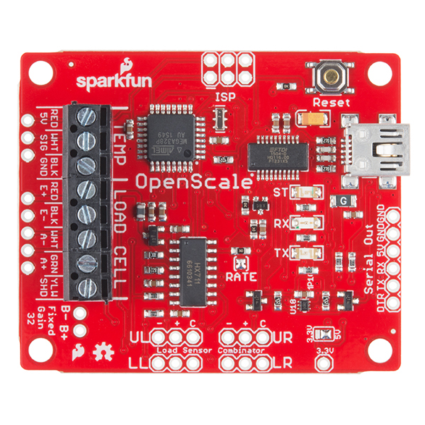
Load cell measurements can be off by +/- 5% due to a range of things including temperature, creep, vibration, drift, and other electrical and mechanical interferences. Before you install your scale, take a moment and design your system to allow for easy calibration or be able to adjust the code parameters to account for these variations. The HX711 Load Cell Amplifier accepts five wires from the load cell. These pins are labeled with colors; RED, BLK, WHT, GRN, and YLW. These colors correspond to the conventional color coding of load cells, where red, black, green and white wires come from the strain gauge on the load cell and yellow is an optional ground wire that is not hooked up to the strain gauge but is there to ground any small outside EMI (electromagnetic interference).